.webp)
Overview: Understanding Failure Mechanisms and Prevention
Tilt cylinder failures rarely result from isolated defects or single causative events. Rather, failures develop through cumulative degradation of components subjected to high-pressure hydraulic cycling, contamination exposure, thermal stress, and mechanical wear over extended operational periods. Understanding the specific mechanisms by which cylinders fail—and the environmental and operational factors that accelerate failure onset—enables maintenance teams to implement targeted prevention strategies that dramatically extend component lifespan and eliminate preventable catastrophic failures.
Analysis of thousands of tilt cylinder warranty claims and service records reveals consistent failure patterns: seal degradation accounts for approximately 35-40% of failures, internal pressure losses from seal wear cause another 20-25%, rod surface damage and scoring represents 15-18% of failures, while structural damage (dents, cracks, bent rods) accounts for 8-12% and installation/contamination-related failures comprise 10-15%. Each failure category correlates with specific operational or maintenance factors that, when properly controlled, can reduce failure incidence by 70-85% compared to unmanaged operations.
Failure Pattern 1: Accelerated Seal Degradation and Rapid Wear
Seal degradation represents the single most common tilt cylinder failure mechanism, accounting for over one-third of all reported failures. Seals degrade through multiple concurrent mechanisms: thermal expansion from elevated fluid temperatures, chemical attack from fluid additives or contamination, mechanical wear from piston rod surface imperfections, and pressure cycling stress that progressively hardens elastomer materials until they lose sealing capability.
Root Causes of Accelerated Seal Wear:
High Fluid Temperature: Hydraulic fluid temperature directly determines seal material longevity. For every 10°C (18°F) increase above the recommended maximum operating temperature (typically 60°C / 140°F for petroleum mineral oil), seal life reduces by approximately 50%. Facilities operating cylinders at sustained temperatures of 70-80°C (158-176°F) experience seal failure within 12-18 months, compared to 36-48 months at properly controlled 50-60°C (122-140°F) operating temperatures. Root causes of excessive temperatures include: inadequate reservoir cooling capacity for duty cycle demands, blocked reservoir cooler fins from dust and debris accumulation, pump oversizing creating unnecessary pressure relief bypass and heat generation, and lack of thermal monitoring that allows gradual temperature creep.
Contaminated Hydraulic Fluid: Particulate contamination in hydraulic fluid directly attacks seal surfaces, creating microscopic scratches and wear patterns that accelerate degradation. ISO Cleanliness Code particle counts above 19/17/14 (measuring particles >4 microns, >6 microns, and >14 microns respectively) dramatically accelerate seal wear. Contamination sources include: inadequate filtration with filters not rated to ISO 16/14/11 or finer, leaking seals and piston rods allowing environmental dirt ingestion, degraded filter media from extended service intervals exceeding manufacturer recommendations, and open reservoir designs allowing dust and moisture ingestion during normal operation.
Incompatible Fluid or Seal Material Selection: Using hydraulic fluid incompatible with seal materials causes rapid seal swelling or shrinkage. Installing cylinders with nitrile seals into systems using biodegradable HETG fluid causes complete seal swelling and failure within hours. Conversely, using petroleum mineral oil in systems specified for biodegradable fluid creates environmental contamination and seal leakage as seals shrink. Seal material must be explicitly verified during cylinder procurement: standard petroleum systems use nitrile seals; biodegradable systems require PTFE or polyurethane seals; high-temperature applications above 80°C require Viton or specialty elastomers.
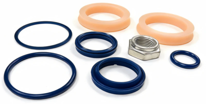
Prevention Strategies: Implement temperature monitoring and maintain fluid within 50-60°C (122-140°F) operating range through proper cooler sizing, routine maintenance of cooler fins, and biannual reservoir cleaning. Upgrade filtration to ISO 16/14/11 or finer (commonly recommended 10/8/5 for precision equipment) and establish filter change intervals at 80% of manufacturer-rated capacity rather than maximum rated life. Perform quarterly hydraulic fluid sampling and ISO cleanliness testing to verify contamination levels remain acceptable. Explicitly document hydraulic fluid type and seal material compatibility at equipment startup and verify every replacement cylinder specification matches original equipment requirements.
Failure Pattern 2: Piston Rod Surface Scoring and Seal Damage
The piston rod—the hardened steel shaft connecting the piston to external load—must maintain mirror-smooth surface finish to prevent seal damage during extension and retraction cycles. Any surface irregularities—scratches, corrosion pits, scoring marks, or dents—create wear paths that accelerate seal degradation and eventually lead to pressure loss and leakage.
Common Rod Scoring Causes:
Particulate Contamination Ingestion: When contaminated hydraulic fluid enters the piston cavity, abrasive particles create microscopic scratches on the rod surface as the piston extends and retracts. These scratches concentrate stress on seal edges, initiating progressive wear that eventually penetrates the seal material. This mechanism typically manifests as slowly increasing leakage over weeks or months, as scratch depth progressively damages the seal coating.
Installation Damage and Misalignment: Improper cylinder removal or installation—particularly rough handling that dents the rod or misalignment stress during reinstallation—creates permanent surface damage. Bent rods or cylinders installed at incorrect angles concentrate stress on specific sections of the rod circumference, causing accelerated wear in those localized areas. Even minor misalignment (2-3 degrees off-axis) creates cumulative wear stress that shortens seal life by 30-50%.
Corrosion and Oxidation: Piston rods exposed to moisture-laden environments (outdoor storage, high-humidity facilities, proximity to washdown areas) develop surface corrosion that degrades the protective chrome plating. Once corrosion penetrates the base metal underneath, rapid rust formation creates pitting that attacks seals. Moisture contamination in hydraulic fluid accelerates this corrosion process dramatically.
Rod Wiper Seal Failure: The wiper seal located at the cylinder head’s outer surface prevents external dirt and moisture from entering the piston cavity during extension cycles. When the wiper seal degrades or becomes damaged, external contamination ingests directly into the cylinder, depositing abrasive particles onto the rod surface. Wiper seal failure often precedes catastrophic seal failure by weeks, providing an early warning opportunity for preventive intervention.
Failure Pattern 3: Pilot-Operated Check Valve Degradation
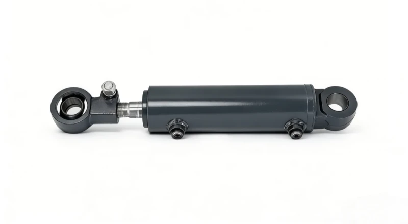
Double-acting tilt cylinders incorporate pilot-operated check valves integrated into the cylinder end caps or manifold assembly. These precision valves prevent pressure loss in both directions, maintaining mast position when tilt controls are neutral. Check valve degradation manifests as “rod drift”—the gradual movement of the mast forward or backward without operator input—which can create load instability and safety hazards.
Check Valve Failure Mechanisms:
Sludge and Particle Accumulation: Contaminated hydraulic fluid deposits sludge and particulate matter inside valve bores, preventing smooth spool movement and allowing pressurized fluid to bypass around valve seats. This leakage typically develops gradually, with drift becoming noticeable only after significant valve wear has occurred. Once sludge accumulation starts, degradation accelerates as deposits create friction points that increase spool resistance.
Pilot Port Restriction: The pilot ports that control spool actuation can become partially blocked by contamination, reducing pilot pressure and preventing full valve closure. Partial pilot pressure results in proportional valve opening that allows controlled leakage without complete pressure loss—manifesting as slow drift rather than rapid pressure equalization.
Seal Erosion on Valve Spools: High-velocity fluid flow across valve seals creates erosion patterns that progressively enlarge flow passages. This erosion process creates a self-reinforcing failure mode: increased flow creates higher velocity, which accelerates erosion, which increases flow further. Once erosion begins, failure typically progresses to complete valve incapacity within 200-400 operating hours.
Prevention Strategies: Maintain hydraulic fluid at ISO 17/15/12 or finer cleanliness (preferably 16/14/11) to prevent sludge accumulation in pilot ports. Perform quarterly hydraulic sampling and fluid analysis to verify cleanliness and detect early signs of contamination before valve damage occurs. Replace hydraulic filters at 80% of rated capacity rather than maximum rated life, ensuring that filtration efficiency remains high throughout service interval. Schedule biannual valve maintenance including pilot port cleaning and seal inspection—preventive valve servicing ($400-$600) is far more economical than catastrophic failure requiring cylinder replacement ($8,000-$12,000).
Failure Pattern 4: Structural Damage and Pressure Excursions
Structural failures—including dented barrel, cracked end caps, bent rods, and ruptured welds—typically result from extreme pressure excursions, severe impact damage, or manufacturing defects. While less common than seal degradation, structural failures often result in immediate complete failure and safety hazards requiring emergency equipment shutdown.
Pressure Excursion Mechanism: Sudden pressure spikes above rated limits (from control valve malfunction, system water hammer, or load shock) create internal stress concentration exceeding cylinder design limits. Repeated pressure excursions above 110% of rated pressure progressively work-harden the aluminum or steel end caps until micro-cracks form. These cracks remain invisible during normal operation but can rapidly propagate into catastrophic failure when subjected to another pressure spike.
Impact Damage from Rough Handling: Dropping cylinders during installation, hitting them against frame structures during replacement, or driving heavy equipment over cylinders creates dents and scoring that stress-concentrate internal pressure loading. A dent reducing the barrel diameter by 20-30% in a localized area increases pressure stress by 2-3x in that region, potentially exceeding material yield strength and causing rupture.
Stress Corrosion Cracking: Particularly in cylinders made from aluminum alloys, exposure to chloride-containing environments (saltwater facilities, de-icing salt residue, marine operations) combined with high pressure creates conditions for stress corrosion cracking. Tiny surface cracks form and progressively propagate under continued pressure cycling, eventually resulting in rupture. This failure mode is particularly insidious because cracks remain undetectable through visual inspection until catastrophic propagation occurs.
Failure Pattern 5: Installation and Commissioning Errors
A significant percentage of early cylinder failures (within first 50-100 operating hours) result from installation errors rather than manufacturing defects. Contaminated fluid introduction during installation, incorrect hose connection, inadequate fastener torque, or misalignment during mounting creates stresses that precipitate rapid seal failure and pressure loss.
Common Installation-Related Failures:
Particle Contamination During Installation: Allowing dust or debris to enter open hose ends or port connections during disconnection/reconnection directly contaminates the cylinder internals. Particles typically embed in piston seals, creating wear paths that initiate rapid degradation. Cylinders exposed to contamination during installation frequently fail within 50-200 operating hours, long before normal wear patterns would cause failure.
Reversed or Incorrect Hose Connections: Cross-connecting extend and retract hoses results in reversed mast control operation—particularly dangerous if not immediately detected during commissioning. Even if corrected before extended operation, misconnection typically creates pressure spikes and control valve stress that damages internal components.
Cross-Threaded Hose Fittings: Connections that appear secure but are actually cross-threaded allow slow internal leakage while maintaining outward appearance of integrity. Internal leakage creates pressure loss and seal damage, typically manifesting as gradual performance degradation over 100-300 hours.
Misalignment and Installation Stress: Cylinders installed at angles exceeding 5-10 degrees from design position create bending stress on the piston rod and uneven seal loading. This misalignment stress concentrates wear on seal edges, typically causing failure within 200-400 hours of operation.
Prevention Strategy: Implement mandatory commissioning procedures including: 50-hour break-in period at low pressure (1,500 PSI or lower) with careful operational monitoring, comprehensive pressure testing before and after commissioning documenting baseline performance metrics, contamination testing of hydraulic fluid immediately after installation and again after initial 50-hour operation, and detailed installation documentation photographing connection configuration for reference during future service.
Proactive Monitoring and Early Detection Strategies
The most effective failure prevention strategy is early detection—identifying degradation in initial stages before catastrophic failure occurs. Proactive monitoring enables scheduled maintenance interventions ($400-$800 for seal replacement or valve servicing) that prevent emergency replacements ($8,000-$12,000 plus downtime costs). Modern condition monitoring techniques enable detection of developing problems weeks or months before complete failure.
Recommended Monitoring Procedures:
Monthly Visual Inspection: Inspect cylinders for external weeping or fluid accumulation that indicates seal degradation. Small moisture films at the rod wiper area are acceptable initial break-in indicators, but streams of fluid warrant immediate investigation. Look for signs of corrosion, impact damage, or hose deterioration that precedes failure.
Quarterly Pressure Testing: Connect pressure gauges to tilt circuit and document pressure readings under standard loads. Compare to baseline established during installation commissioning. Pressure decreases exceeding 10% typically indicate internal leakage from seal wear, signaling that seal replacement should be scheduled within 30-60 days.
Biannual Hydraulic Fluid Analysis: Send hydraulic samples to specialized fluid analysis laboratories ($50-$75 per sample) for ISO cleanliness testing, viscosity verification, acid content analysis, and particle composition identification. Cleanliness trends showing progressive contamination increase indicate filter problems or seal leakage requiring intervention. Acid content spikes often precede catastrophic fluid degradation and seal failure.
Operational Performance Benchmarking: Measure tilt cycle times (time from full backward to full forward mast position) monthly. Consistent 15-20% increases in cycle time over 3-6 month periods indicate gradually increasing internal leakage or control system restrictions. Performance tracking enables intervention scheduling before complete loss of function.
Establishing Comprehensive Failure Prevention Programs
Effective failure prevention requires systematic integration of multiple strategies: temperature management, filtration upgrades, proactive monitoring, scheduled maintenance, proper installation procedures, and environmental contamination control. Facilities implementing comprehensive programs typically reduce tilt cylinder failure rates 70-85% compared to reactive management approaches, generating annual savings of $15,000-$40,000 on a 20-forklift fleet through prevented emergency repairs and extended component lifespan.
Professional consultation can help optimize failure prevention strategies specific to your facility’s operational profile, equipment fleet composition, and environmental conditions. Contact tiltcylinder.net’s technical team at our contact page to discuss condition monitoring implementation and failure prevention program design. Visit our resource center for additional technical guidance, and explore compatible bearing systems documentation for integrated equipment performance optimization.
Conclusion: Root Cause Understanding Enables Effective Prevention
Tilt cylinder failures follow predictable patterns rooted in specific environmental and operational factors: seal degradation from thermal stress and contamination, rod surface damage from misalignment and contamination, check valve failure from sludge accumulation, structural damage from pressure excursions and impact, and installation errors from contamination and misalignment. Understanding these failure mechanisms enables maintenance teams to implement targeted prevention strategies that address root causes rather than repeatedly replacing cylinders damaged by recurring failure patterns.
Facilities that transition from reactive crisis management to proactive failure prevention achieve dramatic improvements in equipment reliability, operational consistency, and total cost of ownership. The disciplined approach—combining temperature and contamination control, pressure system monitoring, installation procedure compliance, and early detection through condition monitoring—requires upfront investment in procedures and training but generates compelling returns through prevented failures and extended component lifespan. Professional tilt cylinder management transforms maintenance from unpredictable expense into controlled operational cost, enabling predictable budget forecasting and superior equipment availability.