A 2026 Engineering Compendium on Aeration Physics, Adiabatic Compression, and Precision De-Aeration Protocols for High-Load Actuators.
In the hydraulic domain, oil is treated as an incompressible medium. However, the presence of even 1% entrained air by volume transforms a precision actuator into a dangerous, elastic spring.
As we move into 2026, the complexity of high-reach aerial platforms, high-tonnage crawler cranes, and automated forklift fleets has reduced the tolerance for system “sponginess” to absolute zero. Air contamination is not merely a nuisance; it is a catalyst for adiabatic compression (micro-dieseling), which destroys seals and oxidizes oil at a molecular level. At tiltcylinder.net, our EP series cylinders are designed with high-integrity internal geometry to facilitate fluid laminar flow, but the installation and maintenance phase remains critical. This guide provides an exhaustive engineering protocol for identifying, bleeding, and preventing air ingress in heavy-duty hydraulic circuits. By mastering these de-aeration techniques, fleet managers can ensure 20MPa+ stability and reduce unplanned maintenance costs by over 40%.
Fluid Dynamics: The Compressibility Crisis
The fundamental principle of hydraulics is Pascal’s Law: pressure exerted on a confined fluid is transmitted undiminished. This holds true for liquids but fails for gases. Air is highly compressible. When trapped in a forklift tilt cylinder or a crane outrigger jack, air acts as a mechanical spring. Under load, the air compresses, causing the rod to retract or “bounce.”
In 2026, this lack of rigidity is a primary cause of Dynamic Load Instability. For an Aerial Work Platform (AWP) extended to 40 meters, a 1% compression at the base cylinder is amplified into a 1-meter sway at the basket. Furthermore, trapped air leads to Cavitation. As air bubbles move from high-pressure zones to low-pressure zones (such as a control valve orifice), they implode. These implosions generate localized heat spikes of up to 1,000°C and microscopic shockwaves that pit the Ra 0.2µm mirror finish of our cylinder bores.
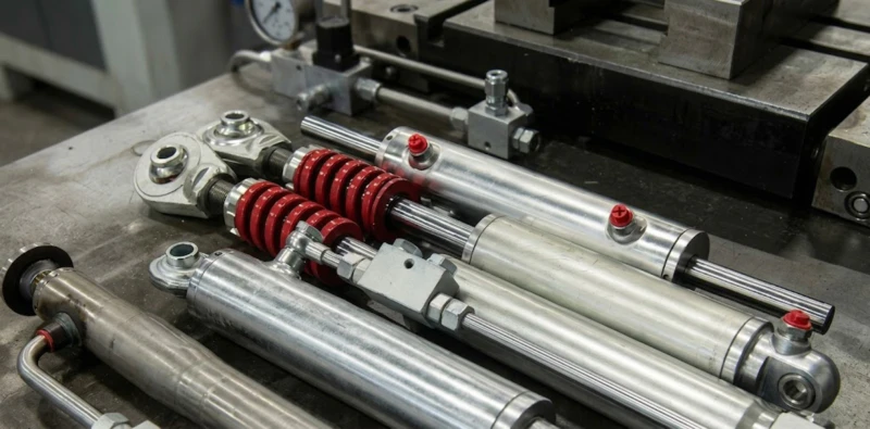
EP Series Precision Aeration Defense
Laminar Flow Ports
Optimized port geometry prevents fluid turbulence, reducing the risk of air entrainment during high-speed cycle times.
Zero-Void Piston
Piston head designs eliminate internal “air pockets,” ensuring that trapped gases are forced toward the ports during bleeding.
High-Rigidity Steel
ST52.3 seamless barrels resist the vibratory fatigue caused by cavitation-induced shockwaves in older systems.
Mirror-Bore Finish
Ra 0.2µm surfaces minimize friction-induced oil heating, maintaining fluid stability and preventing air-outgassing.
Identifying Air Ingress: The Red Flags
Before initiating a bleeding protocol, maintenance professionals must distinguish between different symptoms of aeration. In the 2026 fleet management environment, these three indicators are non-negotiable signs of air contamination:
- The “Banging” Noise: Known as knocking, this indicates cavitationimplosions within the cylinder manifold or valve block.
- Elastic/Spongy Controls: If the mast or boom responds only after a significant delay or exhibits a “springy” motion under load, the fluid has been aerated.
- Milky/Foaming Fluid: Cloudy oil in the reservoir is a sign of Entrained Air. This is often caused by a leaking suction line or a failing pump shaft seal.
- Localized Overheating: If a cylinder barrel is hot to the touch while the rest of the machine is cool, it indicates internal air compression at the rod head.
The Universal De-Aeration Protocol: A Step-by-Step Guide
Properly bleeding a system requires more than just cracking a fitting. Follow this engineering-standard protocol to ensure 100% fluid purity:
Phase 1: Gravity and Low-Pressure Priming
Fill the reservoir to the maximum line. With the engine idling at the lowest possible RPM, cycle the cylinders 50% of their stroke multiple times. Do not hit the internal mechanical stops yet, as high pressure can “shatter” air into millions of micro-bubbles (emulsion), which takes 24 hours to settle.
Phase 2: The “Vertical Elevation” Technique
For crane luffing cylinders or AWP booms, raise the boom to the highest possible vertical angle. Air naturally migrates to the highest point in the circuit. Wait 10 minutes for the air to collect at the rod-end or port-head before proceeding.
Phase 3: Bleed Point Execution
Locate the bleed screws or crack the highest fitting (with the machine off and load mechanically supported). Use a clear bleed-hose and container. Observe the fluid. Continue the process until the oil is “solid” and free of bubbles.
Phase 4: Full-Load Validation
Once air is evacuated, cycle the cylinder through its full stroke five times at 1.5x working speed. Monitor the reservoir level; as air is removed, fluid levels will drop.
Preventing Air Ingress: Designing for Longevity
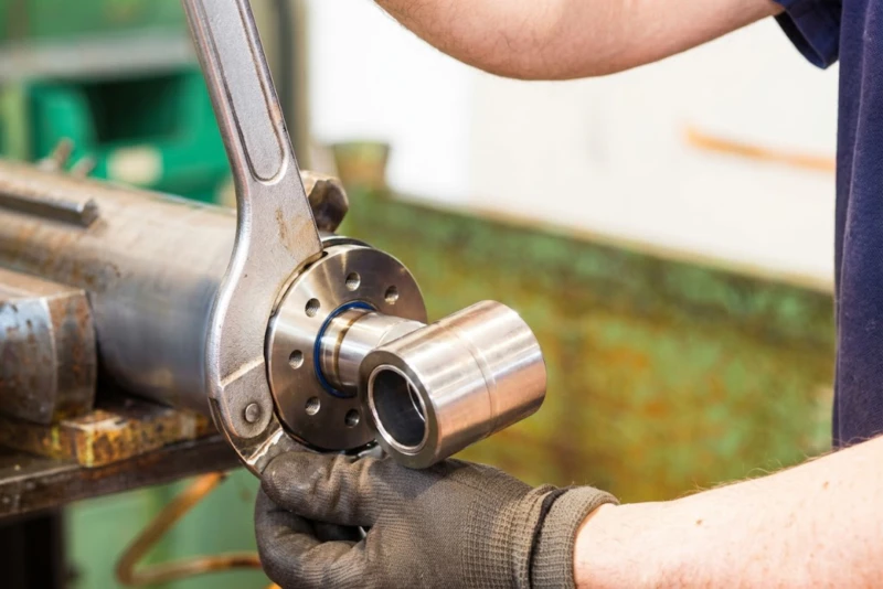
While bleeding fixes the symptom, preventing ingress addresses the root cause. In 2026, the most common source of “re-aeration” is the suction-side plumbing. If a clamp on the pump-inlet hose is slightly loose, the high vacuum created by the pump will “suck” atmospheric air into the oil stream without showing an external leak.
At tiltcylinder.net, our manufacturing process (as seen in our Factory Showcase) utilizes automated ultrasonic testing to verify that port welds and trunnion fusions are 100% airtight. For fleet owners, we recommend a 500-hour inspection of all suction-line bulkhead fittings. By maintaining a vacuum-tight seal on the low-pressure side, you eliminate 90% of all air-related hydraulic failures.
.webp)
Economic Intelligence: The ROI of De-Aeration
Failing to bleed air is a financial liability. In high-reach logistics, “air-bound” cylinders are responsible for approximately $12,000 per year per machine in lost productivity and component wear. By implementing a 1,000-hour bleeding audit, fleet managers can achieve:
- Reduced Oil Oxidation: Trapped air accelerates fluid degradation by 3x, requiring more frequent and costly oil changes.
- Extended Seal Life: Preventing adiabatic compression prevents the “burning” of NOK polyurethane seal lips.
- Improved Fuel Efficiency: Spongy systems waste energy; a rigid hydraulic circuit consumes 10-15% less engine power under load.
- Operator Confidence: Precise, bounce-free controls allow for faster cycle times in ports and construction sites.
Conclusion: Mastering the Medium
As global logistics and infrastructure scaling reach new heights in 2026, the demand for non-compressible stability is absolute. The hydraulic cylinder remains the physical link between industrial ambition and structural reality. At tiltcylinder.net, we combine world-class ST52.3 metallurgy, Japanese sealing excellence, and rigorous de-aeration engineering to provide the actuators that ensure your machines never stop holding their ground. Mastering the physics of air is the first step in ensuring the pulse of your fleet remains steady.
Secure Your Fleet’s Rigid Future
Eliminate sponginess and cavitation from your lifting operations. Connect with our engineering team for specialized EP series solutions or high-volume OEM support.
100% Pressure Hold Tested
Worldwide Technical Support
OEM Fleet Partner


