.webp)
Forklift Tilt Cylinder Specifications: Complete Technical Guide
Essential technical specifications, performance data, and selection criteria for forklift tilt cylinders—comprehensive reference guide for equipment engineers and maintenance professionals.
Overview: Understanding Tilt Cylinder Technical Specifications
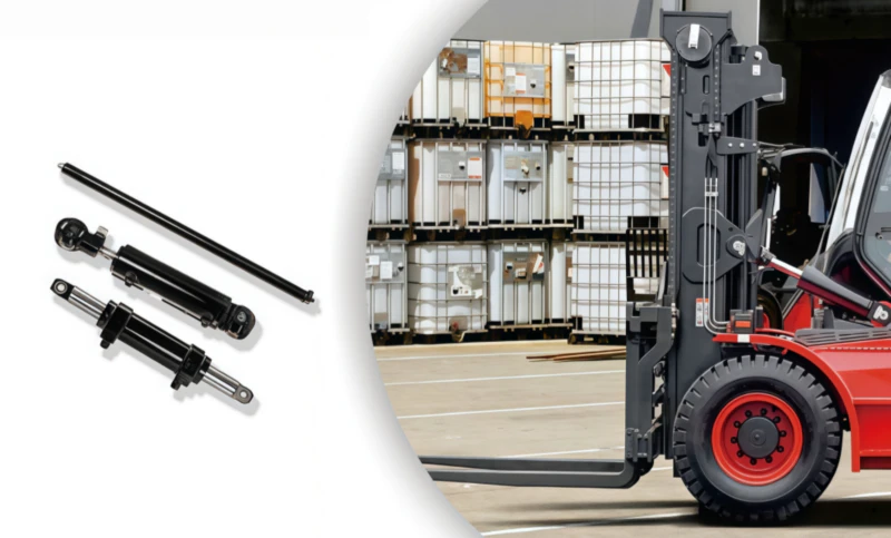
Tilt cylinder specifications define the mechanical and hydraulic capabilities of lifting equipment, determining how effectively a forklift can control mast positioning and handle varying loads. Professional equipment selection, replacement, and performance optimization depend critically on understanding bore diameter, rod diameter, pressure ratings, stroke length, flow requirements, and force output. These technical parameters establish the boundaries of safe operation and enable engineers to match cylinder performance to specific application requirements.
Forklift tilt cylinders come in multiple sizes and pressure ratings designed for different equipment classes, from small pedestrian pallet trucks requiring 1,500 PSI rated cylinders to heavy industrial counterbalance forklifts demanding 2,500+ PSI rated systems. Incorrect specification selection leads to either undersized equipment unable to achieve full tilt range under load, or oversized cylinders wasting energy and increasing operational costs. This comprehensive specifications guide provides the technical knowledge required to evaluate cylinder capabilities, verify equipment compatibility, and select appropriate replacements when cylinder service becomes necessary.
Bore Size and Rod Diameter: Core Cylinder Dimensions
Bore diameter—the interior diameter of the cylinder barrel—represents the fundamental dimension determining force output and working pressure capability. Common tilt cylinder bore sizes range from 60mm (2.36 inches) for small electric pallet jacks to 125mm (4.92 inches) for large counterbalance forklifts. Each bore size corresponds to specific pressure ratings and force output calculations, following international hydraulic standards ISO 1219 and SAE J1935.
Force Calculation Formula:
Force (pounds) = Bore Diameter² (inches) × 0.7854 × Working Pressure (PSI)
A 3-inch bore cylinder operating at 2,000 PSI produces: 3² × 0.7854 × 2,000 = 14,137 pounds extension force. This calculation enables engineers to verify that cylinder force exceeds mast weight and load requirements with appropriate safety factor (typically 1.5x to 2.0x actual load requirements).
Rod diameter determines the piston rod’s mechanical strength and influences retraction force calculations. Standard rod sizes match bore sizes according to ISO 1219 standards, with typical ratios of bore to rod diameter ranging from 1.5:1 to 2.5:1. Double-acting cylinders (where both extension and retraction require force output) use larger rods to maintain adequate surface area for seal contact and piston rod buckling resistance.
Common Tilt Cylinder Bore and Rod Combinations:
| Bore Diameter | Rod Diameter | Typical Application | Rated Pressure |
|---|---|---|---|
| 60mm (2.36″) | 32mm (1.26″) | Pallet Jacks, Small Walkie Stackers | 1,500 PSI |
| 80mm (3.15″) | 45mm (1.77″) | 3,000 lb Forklifts | 1,750 PSI |
| 100mm (3.94″) | 56mm (2.2″) | 5,000-8,000 lb Forklifts | 2,000 PSI |
| 110mm (4.33″) | 63mm (2.48″) | 10,000-12,000 lb Forklifts | 2,250 PSI |
| 125mm (4.92″) | 70mm (2.76″) | Large Counterbalance, Heavy Industrial | 2,500+ PSI |
Stroke Length and Operating Range
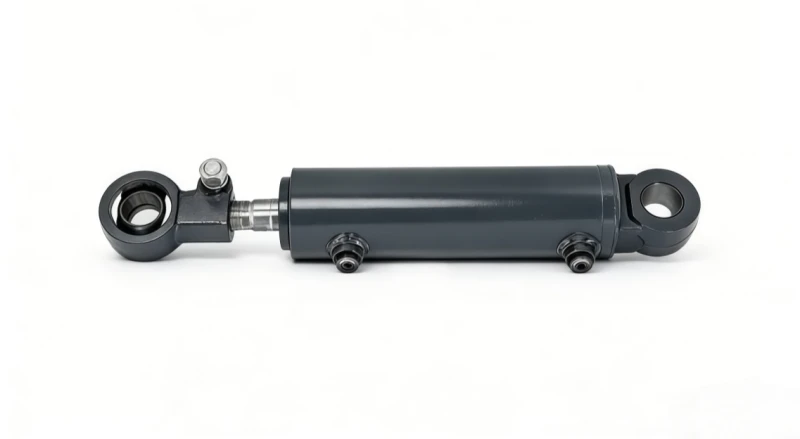
Stroke length defines the maximum extension and retraction distance of the piston rod, directly controlling the range of mast tilt angles achievable. Standard forklift tilt cylinders typically feature stroke lengths between 150mm (5.9 inches) and 350mm (13.8 inches), with longer strokes enabling greater tilt angles and more complete load positioning capability.
Tilt angle range correlates directly to stroke length and cylinder mounting configuration. A cylinder with 200mm stroke mounted at specific spacing provides approximately 45 degrees backward tilt and 12 degrees forward tilt—standard for most industrial forklifts. Specialized applications requiring greater tilt angles (up to 60+ degrees for extreme carriage positioning) utilize longer stroke cylinders or multiple-stage hydraulic systems. Stroke length selection must accommodate full mast tilt range while maintaining adequate force throughout the operating envelope, as force output decreases as the cylinder extends and piston area reduces.
Typical Stroke Length Specifications by Application:
Standard counterbalance forklifts: 200-250mm stroke, achieving 45° backward / 12° forward. Heavy-duty industrial: 250-300mm stroke for improved load positioning. Specialized telehandlers and tilting carriages: 350mm+ stroke for extreme angle positioning. Small pallet jacks and walkie stackers: 150-180mm stroke for compact equipment design.
Pressure Rating and Operating Limits
Working pressure rating defines the maximum hydraulic pressure at which a cylinder can safely operate continuously without seal degradation or structural failure. Forklift tilt cylinders operate across three primary pressure classes: 1,500 PSI (small equipment), 2,000 PSI (standard industrial), and 2,500 PSI (heavy-duty applications). Exceeding rated pressure by even 10-15% accelerates seal wear exponentially and can cause catastrophic seal failure within hours of operation.
System pressure varies based on load, operator demand, and pressure relief valve settings. A loaded forklift under full tilt demand experiences higher pressures than the same equipment at partial load. Pressure relief valves protect the system by diverting excess flow back to the reservoir once pressure exceeds maximum settings, typically 5-10% above rated cylinder pressure. Cylinders rated for 2,000 PSI typically operate with relief valve settings of 2,100-2,200 PSI, ensuring safe operation during peak-load scenarios.
Pressure Rating Standards:
1,500 PSI Class: Designed for light-duty applications, 3,000-5,000 lb capacity equipment. Allows lower cost manufacturing through reduced wall thickness and simpler seal designs. 2,000 PSI Class: Standard industrial rating for 5,000-15,000 lb capacity forklifts. Provides balanced cost, performance, and reliability for general warehouse operations. 2,500 PSI Class: Premium heavy-duty rating for equipment exceeding 15,000 lb capacity or specialized high-performance applications. Requires precision manufacturing and advanced seal materials (PTFE, polyurethane compounds).
Flow Rate and Speed Requirements
Flow rate—measured in gallons per minute (GPM) or cubic centimeters per minute (cc/min)—determines how quickly the tilt cylinder extends and retracts. Forklift tilt functions typically operate at speeds between 8-15 seconds for full tilt range movement, requiring flow rates of 12-25 GPM depending on cylinder bore size and stroke.
Flow Rate Calculation:
GPM = (Bore Area in² × Stroke Length in × Cycles/Minute) / 231
A 3-inch bore cylinder with 8-inch stroke requiring 10-second cycle time needs: (7.07 × 8 × 6 cycles/min) / 231 = 14.6 GPM. Hydraulic pump selection must exceed actual cylinder flow requirements by 10-15% to account for system losses through hoses, fittings, and valves. Undersized pump flow results in slow tilt response complained about by operators; oversized pump flow wastes energy through relief valve bypass and increases cooling requirements.
Mounting Configuration and Pin-to-Pin Dimensions
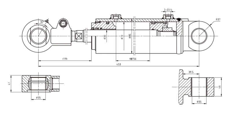
Pin-to-pin dimensions define the overall length of the cylinder in fully retracted position, critical for equipment fit and mounting bracket design. Tilt cylinders feature clevis mount or bracket mount end configurations, with connection points precisely dimensioned to match forklift frame structures and pivot locations. Standard pin-to-pin lengths range from 350mm (13.8 inches) for compact equipment to 800mm+ (31+ inches) for specialized applications requiring longer stroke or specific mounting geometry.
Mounting angle also affects force output and operational characteristics. Cylinders mounted at angles greater than 20 degrees from horizontal experience mechanical advantage reduction and may exhibit instability during rapid actuation. Most industrial forklifts mount tilt cylinders near-horizontal (10-15 degree angle) to optimize force transmission and minimize bending stresses on mast structure. Vertical mounting arrangements found on some specialized equipment reduce available space but provide cleaner aesthetic design and improve protection from contamination.
Seal Material and Temperature Performance
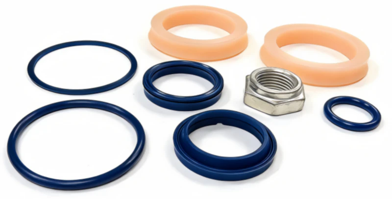
Seal material selection determines the temperature range, fluid compatibility, and operational lifespan of tilt cylinders. Standard cylinders use nitrile (NBR) seals for ambient temperature operations (-20°C to +60°C / -4°F to +140°F) and petroleum-based hydraulic fluid. Specialized applications require alternative materials: PTFE (polytetrafluoroethylene) for extended temperature range and superior chemical compatibility, polyurethane for enhanced wear resistance and precision control in mobile equipment, or Viton (fluoroelastomer) for high-temperature or biodegradable fluid applications.
Seal compatibility with hydraulic fluid type is critical—using biodegradable HETG fluid in a cylinder designed for petroleum-mineral oil causes rapid seal swelling and premature failure. Conversely, attempting to use petroleum oil in systems specifying biodegradable fluid creates environmental contamination risks. Equipment operating in extreme temperatures (arctic cold storage, desert heat, proximity to furnaces) requires specially formulated seals with expanded operating envelope, typically increasing cylinder cost 15-25% but preventing catastrophic field failures.
Standard Specifications for Common Tilt Cylinder Models
The HCYY11112001 model represents a standard industrial tilt cylinder found on 5,000-8,000 pound counterbalance forklifts. Core specifications include: 100mm (3.94 inch) bore, 56mm (2.2 inch) rod, 230mm (9.05 inch) stroke, 2,000 PSI working pressure, 590mm (23.2 inch) pin-to-pin length (retracted), 820mm (32.3 inch) extended length, 18 cc/rev pump displacement for 12 GPM flow at 1,800 RPM, clevis mounting with self-aligning ball joints, nitrile seals for standard petroleum hydraulic fluid, 65 kg (143 lb) dry weight.
The HCYY11112002 steering cylinder demonstrates specifications for equipment requiring higher precision and faster response: 80mm bore, 50mm rod, 180mm stroke, 2,200 PSI rating, 420mm pin-to-pin length, clevis mounts with pilot-operated check valve integration, proportional control spool compatibility for smooth variable-speed steering, 48 kg weight. This model’s design prioritizes smooth response over maximum force output, suited for steering applications requiring continuous fine control rather than discrete tilt positions.
Selecting Replacement Cylinders Using Specifications
When a tilt cylinder requires replacement, matching specifications ensures compatibility and maintains equipment performance. Begin by recording the cylinder’s bore diameter (measure if markings are illegible), rod diameter, stroke length, pressure rating (stamped on cylinder head), and mounting configuration. Cross-reference these dimensions against equipment manufacturer documentation or consult original equipment specification sheets.
Oversizing cylinders increases force output and speed response but wastes hydraulic power and may cause mast instability if force exceeds control valve capability. Undersizing cylinders restricts force output, preventing full load handling or proper tilt angle achievement. Exact specification matching ensures that replacement cylinders perform identically to original equipment, maintaining operator familiarity and system safety characteristics.
For applications where original equipment specifications are unavailable, professional service technicians can measure forklift performance under standard loads and calculate required cylinder specifications using force, pressure, and speed requirements. At tiltcylinder.net, we provide comprehensive specification matching services and custom manufacturing for non-standard applications. Contact our technical team with your cylinder’s current specifications, and we’ll identify the precise replacement or recommend optimized alternatives for your equipment class.
For detailed information on related hydraulic components and mounting standards, explore our resource library and review industry standard rod-end bearing specifications for complete system integration guidance.
Conclusion: Mastering Tilt Cylinder Specifications
Tilt cylinder specifications—bore diameter, rod diameter, stroke length, pressure rating, flow rate, and mounting configuration—define the precise capabilities and operational boundaries of forklift hydraulic systems. Understanding these technical parameters enables equipment engineers to select cylinders appropriate for specific loads and applications, maintain optimal system performance, and make informed replacement decisions when cylinder service becomes necessary. Whether managing fleet maintenance, selecting replacement equipment, or troubleshooting performance issues, a thorough understanding of tilt cylinder specifications provides the foundation for reliable forklift operation and cost-effective equipment lifecycle management.
From small pallet jacks with 60mm bore, 1,500 PSI cylinders to large counterbalance forklifts with 125mm bore, 2,500+ PSI systems, specifications define everything: force output (calculated from bore and pressure), speed response (determined by flow rate), durability (influenced by pressure rating and seal material selection), and compatibility with existing equipment frame and hydraulic systems. Professional equipment selection, installation, and maintenance procedures consistently reference these specifications to ensure safe operation and maximize equipment lifespan and productivity.