Introduction
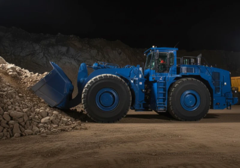
Mining extraction and underground tunnel boring represent some of the most logistically hostile and mechanically punitive environments in the global industrial sector. Whether operating thousands of meters below the surface in active coal faces or executing civil excavation maneuvers through complex subterranean strata, heavy machinery must sustain peak operational availability. High concentrations of abrasive silica dust, corrosive acid mine drainage, relentless high-frequency vibration, and unpredictable structural shock loads define the baseline working parameters for these machines. In these sub-surface environments, equipment availability directly dictates project profitability. A single hour of unplanned downtime halts the entire material hauling chain, idling massive labor crews and incurring high operational penalties.
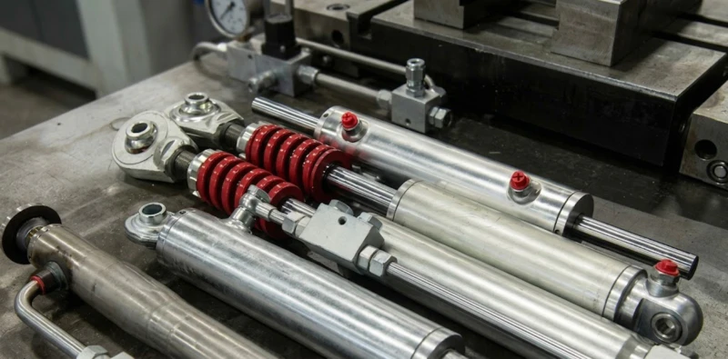
At the absolute core of these heavy excavation systems lies the fluid power infrastructure, where the heavy-duty hydraulic cylinder serves as the critical physical muscle. Every high-tonnage breakthrough force, every micro-alignment structural steering cycle, and every continuous ceiling jacking load depends fundamentally on the output of these linear actuators. Because they operate at the edge of physical material thresholds, understanding their localized mechanics and specific design adaptations is paramount. This technical analysis provides an exhaustive evaluation of heavy hydraulic cylinders across modern mining applications, detailing structural vulnerabilities, advanced sealing architectures, and manufacturing standards required to ensure zero-leak reliability.
Core Application Scenarios Breakdown
Subterranean mining equipment relies on specialized kinematics to execute extreme load-bearing paths. To appreciate the exact performance envelopes required, we must examine the specific mechanics across the most demanding applications.
A
Underground Load-Haul-Dump (LHD) Boom and Tilt Cylinders
Application Description: In trackless underground operations, Load-Haul-Dump (LHD) vehicles are the primary material transport mechanism. Their mechanical layout incorporates twin boom lift cylinders and a high-ratio tilt or dump cylinder. The assembly drives the bucket forward into blasted, un-screened rock faces, curls backward under high force to capture raw ore, and hoists the tonnage to tramming clearance heights before executing high-velocity discharging into mine trucks or ore passes.
Extreme Challenges: LHD operations subject linear actuators to intense dynamic force variations. When the bucket aggressively strikes an unyielding rock face, a severe, instantaneous reverse shock wave propagates straight through the mechanical pins into the extending piston rod, generating microsecond fluid pressure surges well above nominal system limits. Simultaneously, navigating uneven mine floor profiles under full payload causes high-frequency lateral shifting, imposing severe side-loading forces across the cylinder head and internal guide sleeves.
Technical Countermeasures: To mitigate these load profiles, LHD actuators feature forged high-strength steel cap rings and integrated internal dampening valves at both ends of the stroke. These deceleration paths smoothly slow down fluid speed at the stroke boundaries, establishing a high-pressure oil cushion that stops the piston from physically colliding with the steel cap plates.
B
Tunnel Boring Machine (TBM) and Shield Machine Main Thrust Cylinder Arrays
Application Description: Tunnel Boring Machines (TBMs) and soft-ground shield tunneling platforms manage large-diameter underground civil excavation. The propulsion system comprises an array of multiple high-tonnage thrust cylinders arranged circumferentially. These actuators react against previously placed concrete tunnel liner segments, providing the continuous linear thrust necessary to push the rotating cutterhead through solid granite or high-pressure water-bearing strata.
Extreme Challenges: TBM cylinders manage prolonged, high-force static compression cycles. During extended boring tracks, the actuators must maintain continuous working pressures of 35 to 42 MPa for days, testing the anti-extrusion and deformation limits of the primary piston seals. Furthermore, the excavation chamber contains an aggressive mixture of groundwater, abrasive sand slurry, bentonite chemicals, and microscopic rock chips. This slurry continuously coats the extended rods, threatening to shred the rod wipers and enter the internal system upon rod retraction.
Technical Countermeasures: TBM thrust cylinders require specialised piston rod surface engineering. Piston rods are treated with high-velocity oxygen-fuel (HVOF) coatings or advanced laser cladding alloys to establish an exterior shell that resists both abrasive rock slurry and chemical acids. This is combined with heavy-duty mechanical brass scraping blades and multiple front dust exclusion seals.
C
Longwall Mining Hydraulic Roof Support Legs and Advance Cylinders
Application Description: In automated longwall coal extraction, massive hydraulic roof supports provide a temporary protective ceiling across active mining faces. The core of each shield structure features heavy vertical leg cylinders that lift and press the main canopy straight against thousands of tons of overhead rock layers. At the shield base, horizontally integrated advance cylinders pull the armored face conveyor forward before moving the entire multi-ton canopy framework step-by-step into the newly excavated seam.
Extreme Challenges: Roof support legs act as critical static weight retention pillars that face sudden structural stress changes. When the overhead rock structure breaks naturally (known as periodic weighting), the vertical leg cylinders face massive, near-instantaneous fluid load spikes capable of bursting weaker barrel shells. Additionally, the constant presence of high ambient humidity, corrosive coal dust slurry, and sulfur gases creates an active electrochemical environment that triggers hydrogen embrittlement and surface pitting along conventional steel bodies.
Technical Countermeasures: These safety-critical support cylinders utilize high-volume, rapid-response pressure safety valves integrated directly onto the port manifolds. These relief cartridges trigger in milliseconds during roof collapse events, executing controlled high-volume fluid bypass to safeguard the barrel shell from permanent structural deformation.
Core Technical Specifications and Metallurgical Architecture
Operating under high fluid pressures while exposed to severe mineral wear requires a departure from standard commercial cylinder manufacturing. To survive underground conditions, actuators must be engineered with specialized metallurgy and multi-tier sealing architectures to eliminate internal bypass and external leaks.
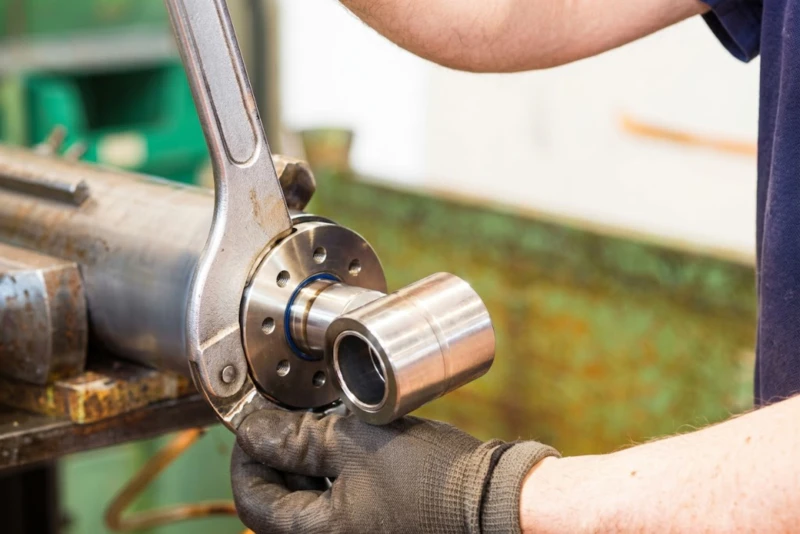
The primary structure of our heavy-duty underground cylinders is manufactured exclusively from carbon-controlled ST52.3 (E355) high-yield strength seamless steel tubing. This material offers exceptional tensile properties and high fatigue limits under cyclic pressure configurations, providing the required yield strength. The internal bore is processed via specialized CNC skiving and roller burnishing to achieve a mirror finish internal bore roughness below Ra 0.2 micrometers, meeting mirror standard configurations. This smooth, plateaued surface micro-topography establishes micro-pockets that trap an even hydrodynamic layer of oil, lowering friction and protecting the seals during fast strokes. The piston rod is machined from high-tensile alloy steel and subjected to induction case-hardening to a uniform depth of 1.5mm to 2.5mm, reaching an external hardness profile of HRC 55 to 60. This hardened shell resists impacts from loose rocks and prevents surface dents. On top of the hardened layer, a 50 micrometer duplex hard chrome matrix ensures superior corrosion resistance against mine water.
To ensure positive fluid separation and prevent position drift under intense pressure spikes, our cylinders feature a high-integrity seal layout integrating premium components for zero internal leakage, utilizing authentic Japanese NOK polyurethane and elastomer compounds:
| Sealing Component | Material and Geometric Strategy | Subterranean Performance Characteristics |
|---|---|---|
| Primary Buffer Seal Ring | PTFE Matrix + Bronze Fill with Elastomeric Ring | Acts as the primary shock absorber, smoothing out 90 percent of instant pressure spikes before they can damage the primary rod seal. |
| Secondary Rod Seal | NOK High-Elasticity AU Polyurethane | Maintains strong lip contact against the rod under extreme temperature variations up to 110 degrees Celsius, providing long-term reliability. |
| Expanded Wear Bands | Reinforced Cross-Linked Phenolic Polymer | Features an expanded surface area designed to support heavy side loads, preventing metal-to-metal contact between the piston and internal barrel. |
| Metal-Clad Scraper Seal | Rigid Steel Case with Tough Nitrile Scraper Lip | Operates like a mechanical blade to clear away abrasive sand slurry, packed mud, and coal scale from the rod during retraction. |
.webp)
Our Core Technical Advantages
Operating equipment in heavy mining sites or deep tunnel projects requires robust component performance. Choosing our technical manufacturing division ensures long-term operational security over constant field maintenance risks.
1V1 Engineering Customization
Whether dealing with ultra-low temperature open-pit mining at negative 40 degrees Celsius or high-acid underground environments, our engineering group custom-tailors wall profiles, alloy properties, and base treatments to your exact needs.
Automated SAW and NDT Verification
We leverage automated Submerged Arc Welding (SAW) systems to establish reliable weld penetration. Every critical structural seam faces mandatory 100 percent Ultrasonic Non-Destructive Testing (NDT) to eliminate internal porosity defects.
Optimized Fleet TCO
By uniting high-yield ST52.3 barrel bodies with authentic Japanese NOK sealing polymers, our heavy-lift cylinders yield a 45 percent reduction in long-term field maintenance costs and prevent sudden fluid pressure loss compared to standard components.
Digital Sensor Integration
To support modern autonomous mining operations, we can integrate explosion-proof (Ex ia) magnetostrictive sensors or LVDT modules inside the rod shaft, enabling real-time stroke position tracking with sub-millimeter precision.
Maintenance Protocol and Troubleshooting Diagnostics
Proactive equipment care is the most effective methodology for extending hydraulic system life and ensuring component safety.
The primary failure mode in heavy underground machinery is abrasive wear causing internal pressure loss. When hard rock particles or coal dust bypass worn wiper lips, they enter the oil stream and create an abrasive slurry. This mixture scores the precision mirror finish of the internal cylinder wall, leading to internal fluid bypass. This bypass causes noticeable boom drift or a slow loss of pressure retention. Maintenance groups must implement strict oil analysis schedules, keeping fluid cleanliness aligned with ISO 4406 16/14/11 hygiene standards. If fluid checks reveal a dark or cloudy appearance, the system requires an immediate oil flush and filter element upgrade. Additionally, maintenance technicians should check the torque on mounting pins, clevis mounts, and spherical bearings every 500 operating hours; asymmetrical alignment or loose tolerances create severe lateral side-loading, which accelerates seal wear and cuts cylinder operating life.
Frequently Asked Questions
Can your hydraulic cylinders adapt to sub-zero open-pit mines or highly acidic underground water environments?
Yes, our cylinders are specifically engineered for these extreme environments. We integrate low-temperature impact-tested alloy steel alongside specialized low-temperature polyurethane seals rated for negative 40 degrees Celsius. For acidic environments, we utilize multi-layer nickel-chromium electroplating or laser cladding coatings to prevent chemical corrosion and sub-surface hydrogen cracking.
What is the maximum nominal working pressure and surge pressure rating for your mining-grade cylinders?
Our standard mining and tunneling cylinders operate at a continuous working pressure of 35 to 42 MPa. To manage the intense pressure spikes common in underground blasting and drilling, the structural wall boundaries are calculated to absorb transient surge pressures up to 60 MPa, ensuring a 4:1 burst safety factor.
What specialized rod coatings do you provide to resist scratches from sharp rock debris or falling coal scale?
We use high-frequency induction hardening to establish a robust HRC 55 to 60 surface case, which we finish with a 50 micrometer duplex hard chrome layer. For extreme conditions, we can apply high-velocity oxy-fuel (HVOF) thermal sprays or specialized tungsten carbide cladding to maximize external surface hardness.
Can your engineering team directly manufacture custom non-standard cylinders directly from our STEP or SolidWorks files?
Yes, we accept direct file ingestion across all major engineering formats, including SolidWorks, STEP, IGES, and AutoCAD designs. Our technical team conducts an initial parametric review to verify tolerance matching and structural clearance parameters before beginning production.
Do you support integrating explosion-proof displacement sensors for automated mining machinery?
Yes, we provide full support for smart digital factory and mining automation. We use precise coaxial deep-hole gun drilling along the center of the rod to house intrinsically safe (Ex ia) or flameproof (Ex d) magnetostrictive linear sensors, providing real-time tracking data accurate to sub-millimeter levels.
What is your standard minimum order quantity (MOQ) and production lead time for custom replacement runs?
We maintain highly flexible commercial policies, supporting operations with low MOQ options starting at 1 unit for prototype testing and legacy rebuild support. Custom engineering layouts generally require 4 to 6 weeks for fabrication, while mass OEM production batches are delivered on a scheduled timeline.
How do your engineers prevent long-stroke boring machine actuators from buckling under extreme compressive force?
Every long-stroke design undergoes rigorous computerized Euler buckling modeling during our initial design checks. We precisely verify structural wall thickness tolerances, choose appropriate cross-sectional rod diameters, and widen internal guide sleeves to maintain absolute axial stability under maximum force profiles.
What physical validation quality testing is performed on your cylinders before they depart the factory?
We operate a rigorous zero-leak test facility. Every completed cylinder undergoes dynamic cycle running, a 100 percent hydrostatic proof pressure hold test at 1.5 times rated capacity, internal bypass metering, and breakaway friction mapping, with full data sheets compiled for client review.
What is your standard aftermarket warranty framework and your support policy for remote international sites?
All our heavy-duty cylinders include a 12-month commercial product warranty. Our technical service center provides remote diagnostic feedback within 24 hours of receiving field data, and we can quickly ship standard seal kits or replacement components from our central inventory to minimize site downtime.
How do you guarantee that a custom outrigger or push cylinder will function correctly with our machine’s existing main hydraulic valves?
During our initial design verification phase, our fluid engineers model fluid flow rates, internal stick-slip oil drag parameters, cushion backpressures, and stroke damping speeds, verifying that the new actuator matches your plant control loop requirements seamlessly.
Conclusion and Strategic Action Call
The mechanical stability and overall uptime of high-capacity mining and underground equipment depends directly on the durability of its core components. Investing in advanced material manufacturing, high-yield ST52.3 seamless barrels, and elite Japanese sealing chemistry is an investment in long-term operational profitability. When machinery operates deep underground or pulls thousands of tons of earth, component security is paramount. If you are seeking highly dependable, custom-designed hydraulic cylinder configurations engineered to survive severe working environments, look no further than our technical production division. Let us transform your design challenges into high-performance industrial assets.


